Hand Diaphragm Pump
Hand Diaphragm Pump
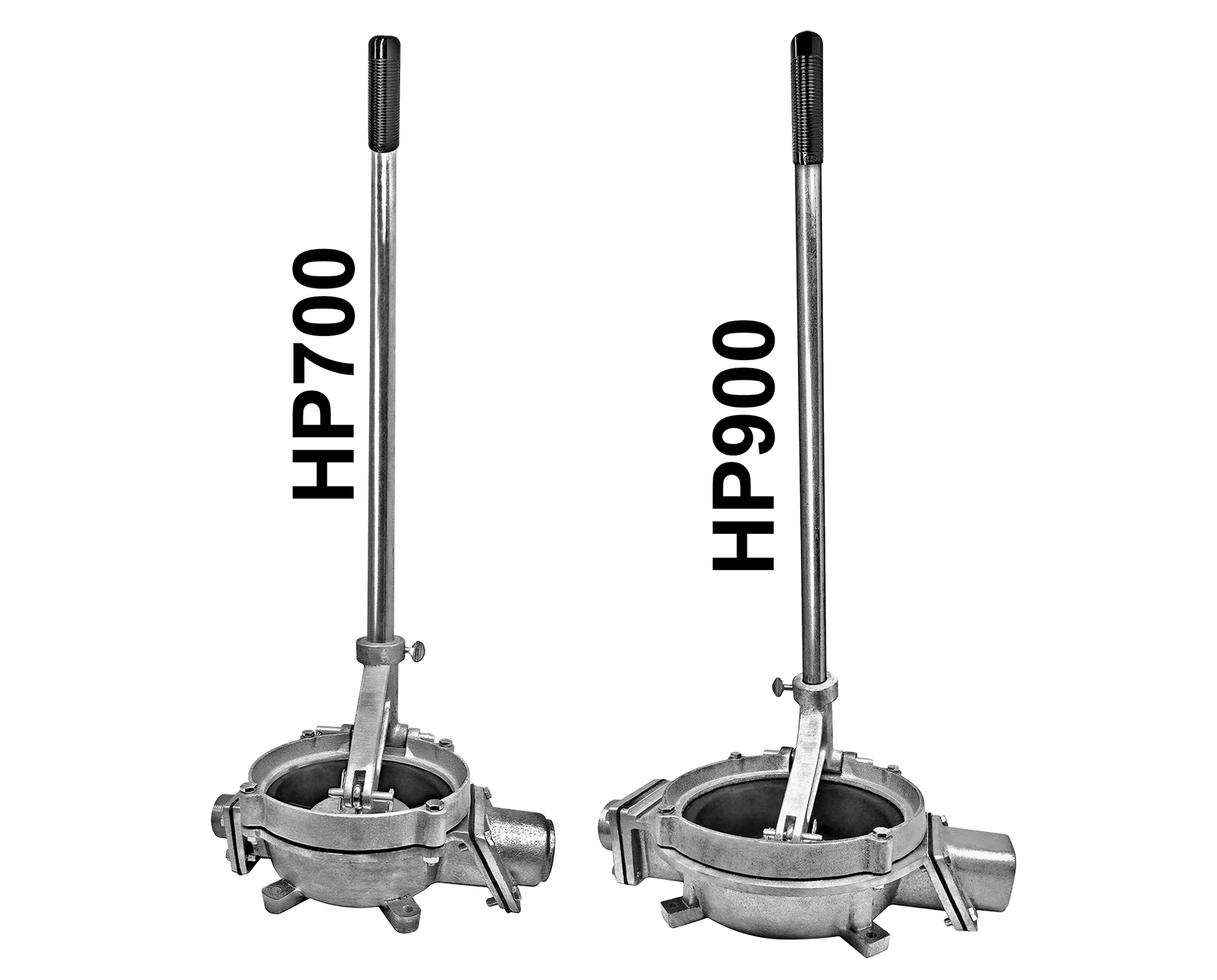
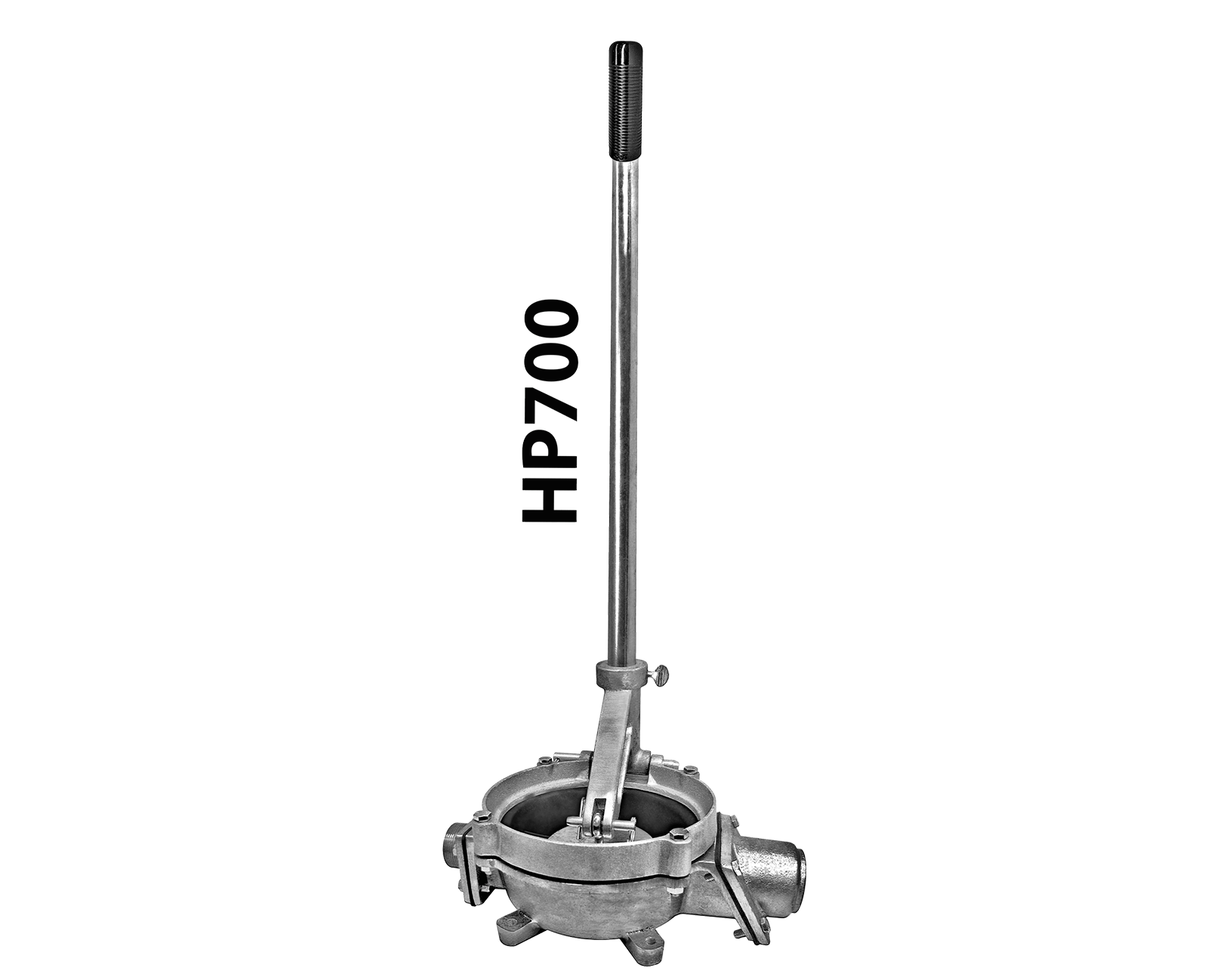
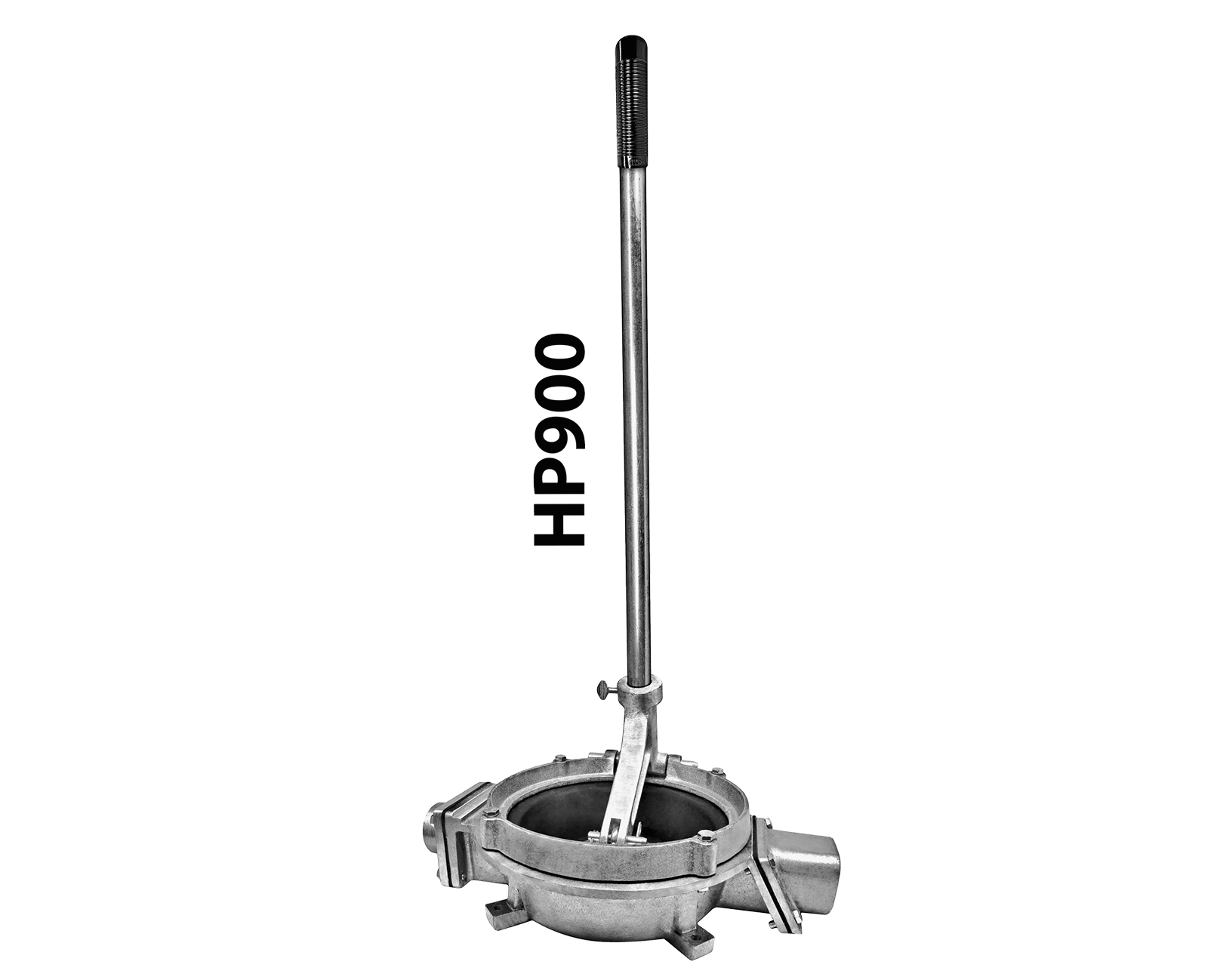
The Hand Diaphragm Pump (HP) is a single-chamber air and liquid pump. The chamber has 2 opening flapper valves for suction and discharge. The diaphragm is actuated by the fulcrum handle bracket, air and/ or liquid is pulled into the chamber through the suction valve and expelled through the discharge valve. The Protek Hand Pump (HP) is portable, lightweight, and dependable.
-
INSTALLATION & OPERATION
- Insert handle into fulcrum, making sure that fulcrum and handle holes align before inserting the fulcrum pin.
- Place pump on a solid foundation that is as close as possible to the fluid that is going to be pumped. (This positioning should make the suction line as short and direct as possible.)
- Attach suction pipes to the suction inlet and to the discharge outlet.
- Suction line must be sloped upward in order to provide continual feed into the pump.
-
SAFETY & RECOMMENDATIONS
- To extend diaphragm and valve life, flush the pump with water after each use.
- Replace the diaphragm and valves that show signs of wear, cracking or corrosion.
-
Troubleshooting
If you cannot get the HP to prime, try one of the following: - Make sure there is no debris left inside where the valves are. Any debris can cause clogging.
- Inspect the diaphragm for any tears or cracks.
- Check the line for any blockage or loops. The line must be straight and not twisted in any way.
- Check all sections of the suction line for air leaks.
- If the eyebolt assembly becomes loose from the diaphragm assembly:
- Remove the bolts which connect the retainer ring and pump body so that the diaphragm assembly can be removed.
- Remove the diaphragm assembly and tighten the jam nut located on the underside of the diaphragm assembly until the bottom jam nut is even with the bottom of the eyebolt.
- Re-assemble the pump by reversing the dis-assembling process. *When re-assembling the pump, have the pump’s discharge side to your left, and make sure that the opening of the eyebolt is facing you.
-
Hand Diaphragm Pump – Parts
DIAPHRAGM ASSEMBLY – #H0707A & H0907A PART# DESCRIPTION H0707C/H0907C Diaphragm H0709 Diaphragm Plate (2 Req.) X0019 Eyebolt w/ Nuts REPAIR KITS HP7RK HP9RK DESCRIPTION H0707C H0907C Diaphragm H0709 H0709 Diaphragm Plate (2 Req.) H0710 H0910 (2 Req.) Discharge Valve (Also Suction Valve for HP900) H0714 – Suction Valve (HP700/HP7RK Only) D0347A D0347A Clevis Pin Assembly H0902A H0902A Fulcrum Pin Assembly X0019 X0019 Eyebolt Assembly X0D11 X0D11 3/8-16″ Jam Nut (2 Req.) X0H21 X0H21 5/16-18″ x 2″ HH Bolt (4 Req.) X0H31 X0H31 5/16-18″ x 1″ HH Bolt (8 Req.) X0H41 X0H41 5/16-18″ Nut (4 Req.) PRIMER CAPACITY CHART MODEL# INLET/ OUTLET CAPACITY MAXIMUM SUCTION LIFT MAXIMUM DISCHARGE HEAD APPROX. NET WEIGHT HP700 1-½” NPT ½ gal./Stroke 20 ft. 10 ft 15 lbs. HP900 2” NPT 1 gal./Stroke 15 ft. 10 ft. 18 lbs.


